- Tutorials
- Design Software
- Electronic (Vinyl) Cutters
- Electronics Projects
- Laser Engraver
- Beginner - Intro to Inkscape for the Epilog Laser
- Beginner - Make Your Own Ruler
- Beginner - CUC Fab Lab Pressfit Boxmaker
- Beginner - Create a key chain
- Beginner - Engrave on Glass
- Advanced - Create a "3D" edge with the "2D" laser cutter
- Advanced - Laser Cutting Paper
- Advanced - Press Fit Box
- Advanced - Engrave an alumninum waterbottle
- Advanced - How to Mark a Zippo with the Epilog Laser
- Advanced - Living Hinges
- Advanced - Laser Moleskine Notebook
- Milling Machines (CNC Routers)
- Other Equipment
- Textile Machines
- 3D Printers
Beginner - CUC Fab Lab Pressfit Boxmaker
Tue, 01/21/2014 - 17:43 — Geph
How to Use the CUC Fab Lab Pressfit Boxmaker
<
By Robert McGrath | v1.1 | 01.2014
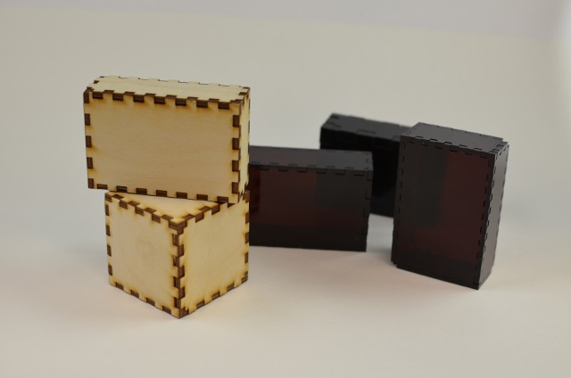
The Pressfit Box Maker program is a tool that helps create pressfit boxes. It is primarily designed to be used in the Champaign Urbana Community Fab Lab, though both the software and the results can be used elsewhere. This program does not completely automate the process, but it can make it much easier to experiment and iterate to work out your design ideas.
The software uses an algorithm to create a drawing of a pressfit box in a PDF file. The result may or may not be exactly what you intended, so you should expect to try it a few times; to test some settings, examine the results, and adjust the settings, until the results are what you want.
Another important feature of the program is that the output is a PDF file that can be modified, e.g., with Inkscape. So: you might create a generic box, save the file, and then customize it with decorative graphics, text, or other modifications. You could, for example, add a hole to one side, to create a simple birdhouse.
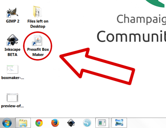
Either way, the boxmaker should make it easier to create pressfit boxes and similar projects at the Champaign Urbana Community Fab Lab. You can find the launcher on the desktop of all PC’s in the lab:
1. Basic Operation: Define Your Box
The first step to creating a box is to set the dimensions (height, width, and depth) of the box. This is entered in the three values on the form. By default, the boxmaker GUI uses millimeters, though you can opt to use inches to describe the box.
It generally doesn’t matter to the software which direction is ‘height’, ‘width’, or ‘depth’. You will get pretty much the same result if you set the size to (10 x 20 x 30), or (20 x 10 x 30) or some other combination of the same sizes.
The box can be any size, though common sense should be applied. Very tiny dimensions are impractical to make. Generally, the side a box must be at least twice the size of the thickness of the material. (Think about it.)
Also, the Epilog laser bed is limited to 12 x 24 inches, so no single part can larger than that. If the parts are so large they don’t all fit on a single 12 x 24 drawing, it will be necessary to manually edit the drawing to create multiple files.
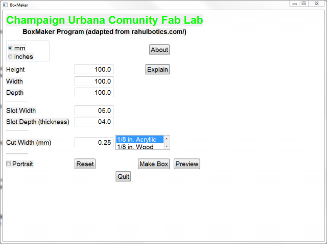
2. Define the Pressfit Tabs and Slots
Once the size of the box is set, the next question is to set the size of the tabs and slots. Note that the software makes all the tabs and slots the same size. That is, all sides will have identically sized tabs to fit into the same sized tabs.
First, the ‘slot depth’ should usually be set to the thickness of the material. This creates a flush fit with the surface of the sides.
The slots/tabs can be any size you want, though common sense should be applied again. Obviously, a tab cannot be larger than the piece itself. (If you have a 20 mm side, how could you have a 35 mm wide tab?) Tabs can’t be too small either, or they will be fragile or just impossible to cut.
In general, tabs/slots should be at least a couple of millimeters wide but considerably smaller than the width of the smallest dimension, so there will be at least a few tabs on the smallest dimension.
When considering the size of the slots, there are two factors to think about.
First, the tabs are laid out by an algorithm, which does its best but is not perfect. The algorithm is tries to lay out tabs and slots of the given size in a reasonable way across all six sides of the box (potentially three different dimensions). In most cases, the tabs do not fit evenly across all the sides, leaving part of a tab or slot at the corner of one or more sides. In this case, the partial tab/slot combination may result in a fragile or ugly joint.
It may be difficult to anticipate in advance how a given combination of dimensions and slot width will work out, so you should examine the preview of the result (see below), and adjust the slot width if needed. For example, a slot width of 3 mm might give a poor result for a width of 116 mm, but 4 mm might work well. It is difficult to know without seeing the result from the algorithm.
One commonly used slot width is to set the tab width to the same value of the slot depth. This yields a very neat set of square tabs and slots. Of course, this may or may not work, if one or more of the dimensions is an awkward number of tab/slots. (Try some examples.)
3. Define an Adjustment for the “cut width”
The final important parameter is the ‘cut width’. This parameter adjusts the tabs and slots by a small amount to account for the material removed by the laser. The larger the number the ‘tighter’ the fit.
The adjustment to use depends on the specific material that will be used. The boxmaker software provides some suggested settings for commonly used materials. However, the precise value may need to be adjusted for a given case. Note that the suggested settings create a very tight fitting box.
Using the cut width is optional. Leaving it to be zero may work OK, especially for flexible materials such as cardboard. You might also want a ‘looser fit’, if you want the box to be able to be dismantled easily. If so, you may want to adjust the cut width to get the fit you want.
For a given project, you may well need to iterate to discover the exact cut width that creates the box you want.
4. The ‘Make’ and ‘Preview’ Steps
When the parameters are set, the ‘Make Box’ button calls the program to generate the box you have defined. If there is a problem, a dialog will pop up with messages.
The program will check for obvious problems. For example, extremely tiny dimensions will be rejected, as will absurd sizes for the tabs.
If all goes well, then a dialog will pop up to save your result in a PDF file. You should give the file a name you can remember, and save it on the Desktop or somewhere convenient.
After the file is saved, you can look at it with the “Preview” button. (You can also use any other PDF viewer).
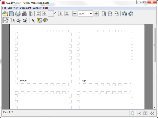
As noted above, there are several things to look at. In particular, check the corners of the pieces, to see if they are reasonable. A common problem is to have a very thin tab at the corner, which will be very fragile.
If there are problems, or you want to try different settings, you can adjust the parameters, and make another box, and iterate.
5. Happy with the Design? Using the results.
When you are satisfied with the box, you can use the PDF file. You might want to write down the settings you use, in case you want to recreate the file later.
When you have a result, you can send the PDF file to the Epilog laser. The results might not be exactly what you want. For example, the fit might be too loose or too tight, or some corners might be fragile.
If so, you can return to the program and adjust the parameters.
You can also edit the PDF file in Inkscape or another program. You might add decorations, rearrange the pieces, or make other changes. When editing the file, try not to magnify or shrink the pieces of the box. This could have the side effect of changing the width of the line, so it would no longer be a vector cut on the Epilog. You would have to manually readjust the line widths.
Thanks
Thanks to Rahul Bhargava who published the original and has made it available open source. Thanks to Andy Jones for initial (heroic) experiments and helping get the software available.
Code
See the documentation and instructions page to get to this.